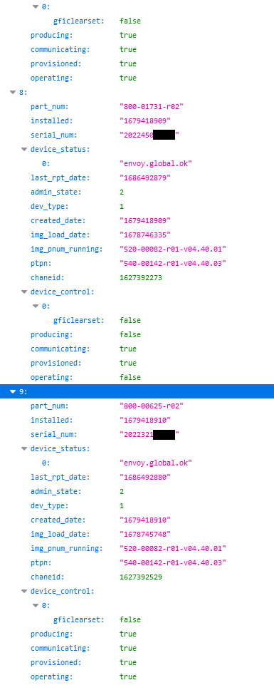
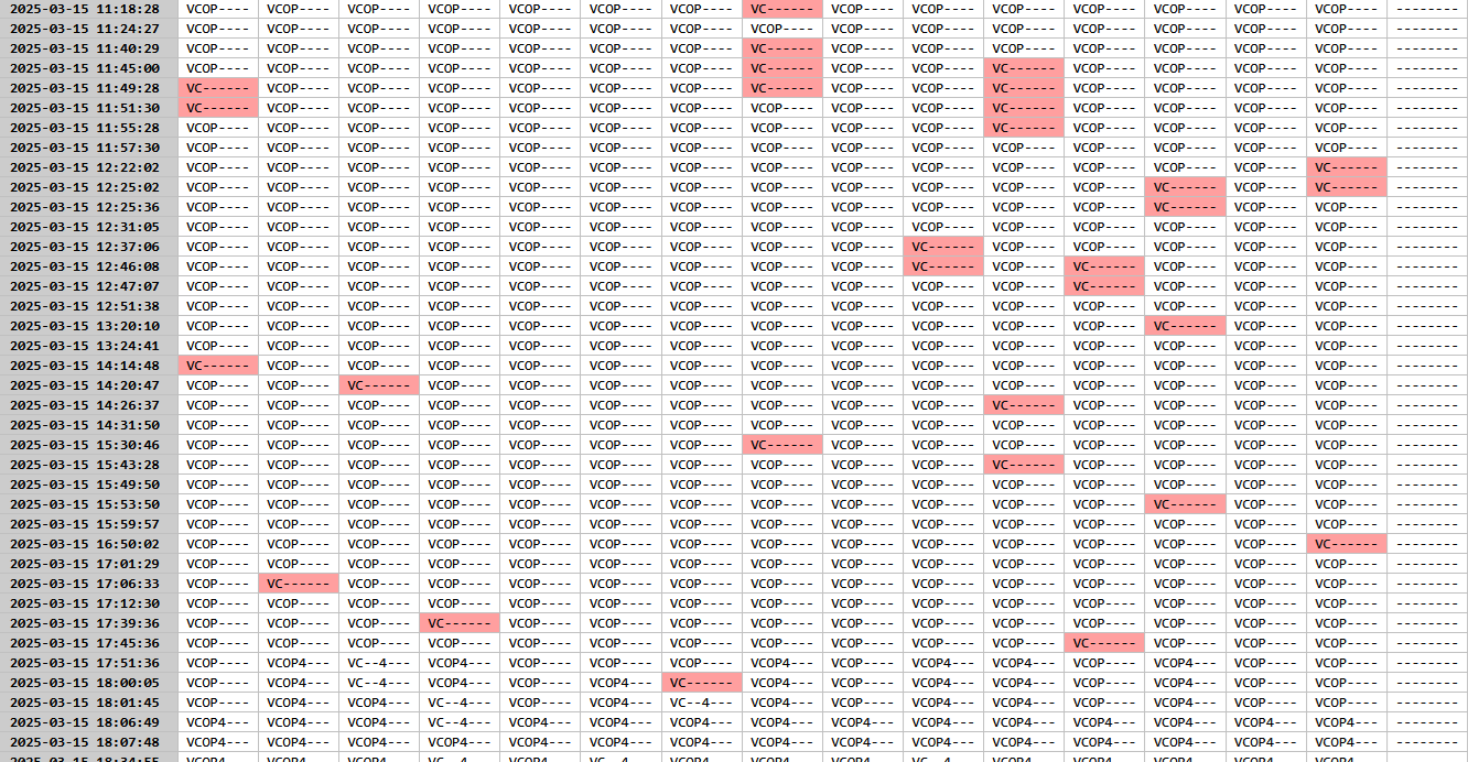
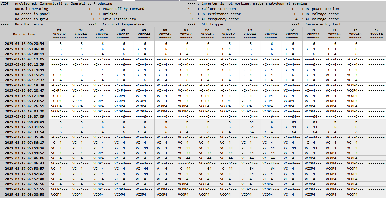
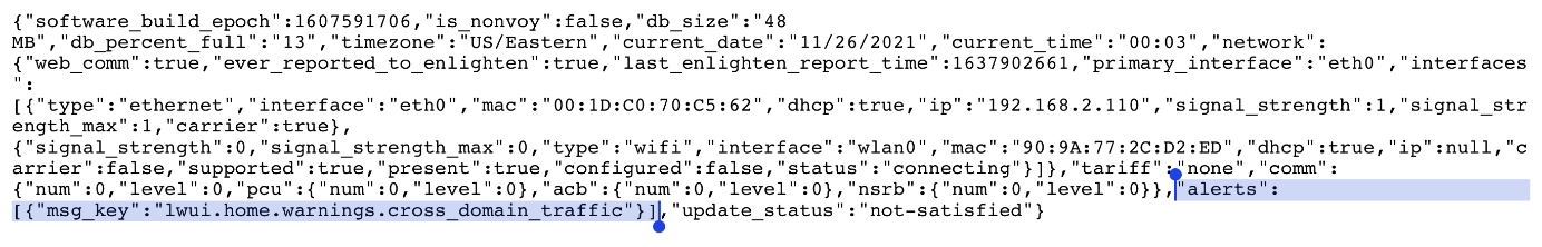
This is the inventory.json data from Enphase Envoy Gateway,
There are 4 flags as producing/communicating/provisioned/operating.
Each flag has true or false value.

Some inverters are showing false for producing/operating flags.
I have tracked the actual production, but, the inverters are producing/operating normally.
Just flags are showing as false.
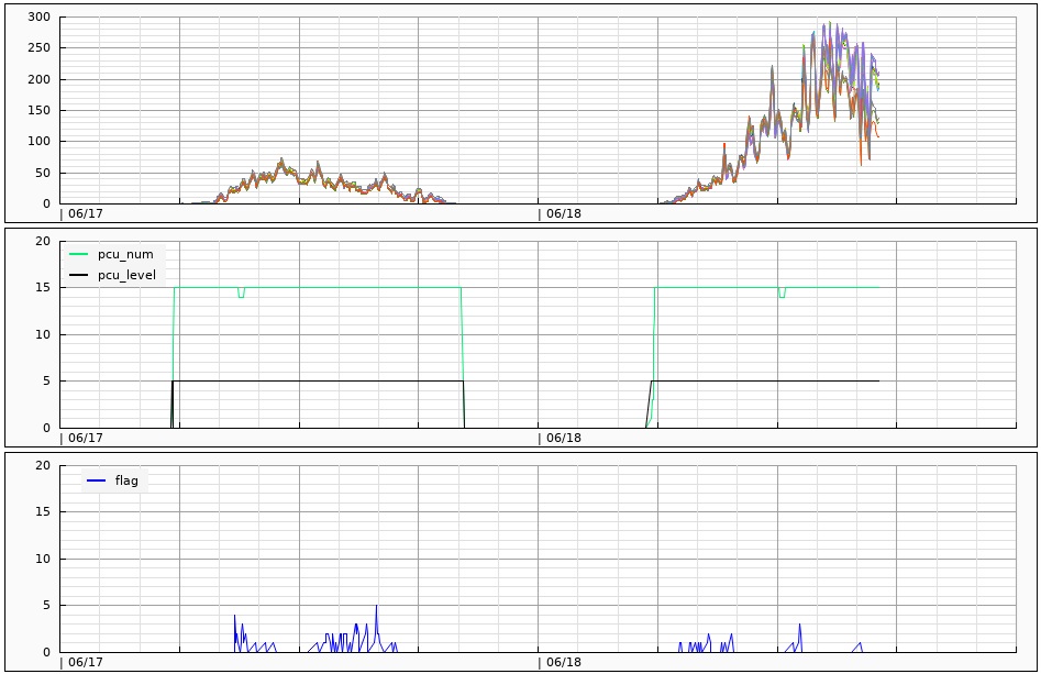
It is showing when the flag error is more happening,
and, I found that is caused with my next door under 'cross-domain-error'
This interference is not happening while low production status such as 0.5kW or lower,
Maybe I am ignoring the flag check when 'low power DC' status,
so, I want to say the flag error is happening but not showing in the graph.
when production power is going over 1kW, the flag error has been gone,
Actually, power line noise is going-up over the signal from my next door,
so, no more interference are happening.
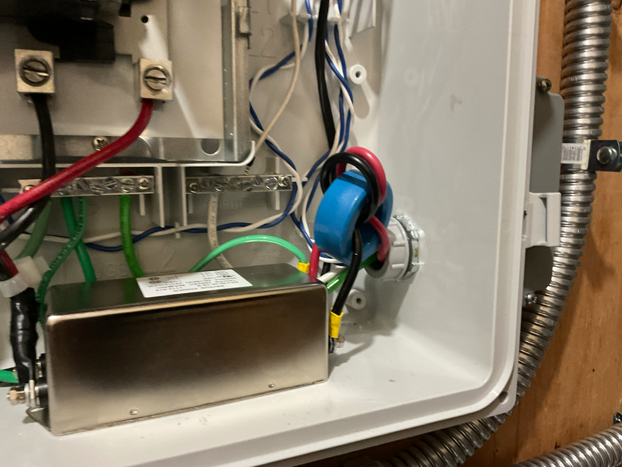
Because some communication loss issue when installed PLC filter, I have removed it.
The X capacitor in PLC filter can reduce the signal level from inverters, and it disturbe a communcation.
after remove the filter, the signal from next door is coming in more easily.
I have increase the line impedance using inductors up to 100Ohm.
But, it can not stop the signal enough because no bypass Y capacitor.
Even can avoid a communcation error between gateway and inverter after removing PLC filter.
There is no clear solution to resolve the communcation conflict with my next door.
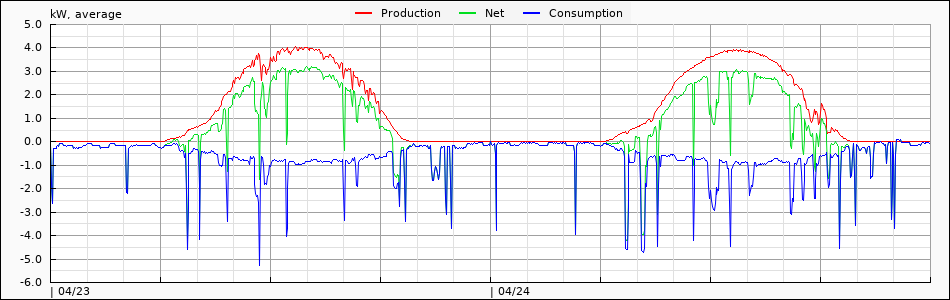
The blue line is the power consumption, and red-line is the production power from Enphase Gateway.
You can see some strange behavior, Power consumption looks line a reflection of production.
High production power stage it is showing much deeper
it can be happening when Consumtion CT connection is no good, or not climped well at L1/L2 line side.
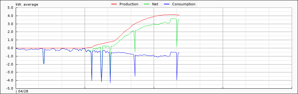
I just fixed the connection of Consumption CT, and the power consumption become normal, it is matched with actual value around 500W.
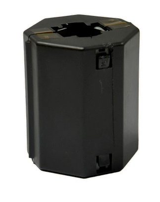
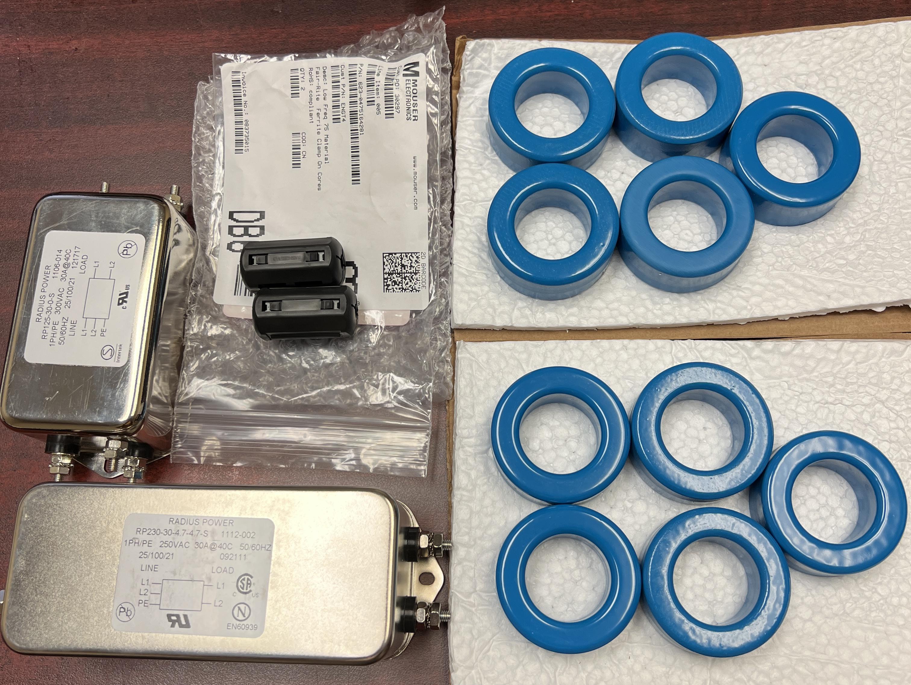
This is the ferrite core 30A/65A
Fair Rite 0475176451 for 65A
Fair Rite 0475164181 for 30A
Those ferrites are not high current model, so, need put a gap
Enphase has applied 0.065mm Kapton Tape one 4 sides, and it makes 0.26mm gap.
This is the reference table
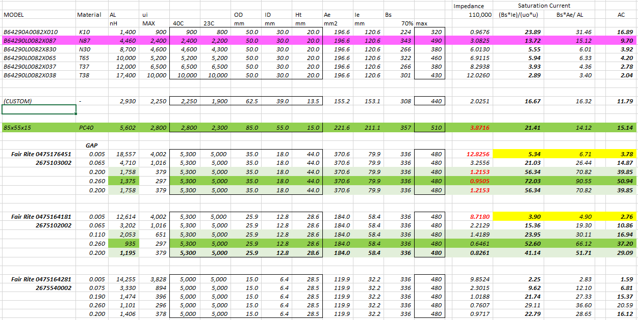
65A model can support upto 72A with 70% of Bs
30A model can support upto 53A with 70% of Bs
I have used 0.1mm x 2 = 0.2mm tape to reduce the gap, and reduced current as 56A.
and, 2 pass widing to increase the impedance 4x, and reduce the staturation current as 28A.
using 4 ferrites, I have set 19Ohm @ 110kHz
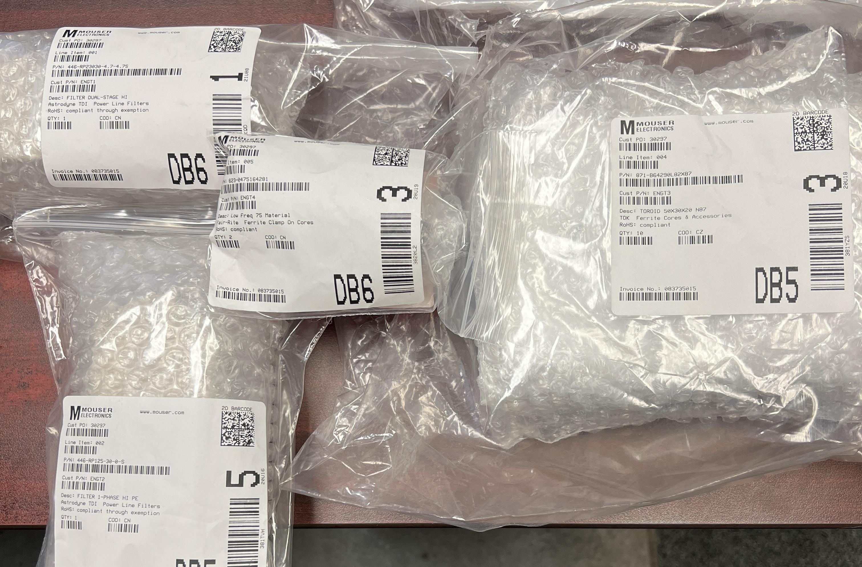
Today, I have received Power Line Filters and Ferrites
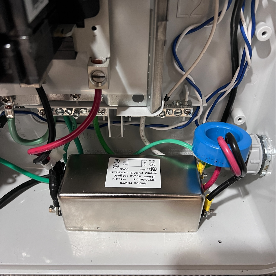
RP125-30-0-S It is single stage power line filter, and there is no Y capacitor, It can avoid a capacitor loss. and, much less power loss while production
RP230-30-4.7-S it is double stage power line filter with 4.7nF Y capacitor. I have RP230-30-10-S at the combiner box. maybe too much to try.
B64290L82X87 TDK 50mm ferrite core, I have used B64290L0082X065. But, I have decided to test with this ferrite becuase some reasons
1) X065 have 8~9A staturation current, but, this one have 21-22A
2) X065 has 10uH, and X087 has 4.460uH, so, I need more ferrites to get a similar result
Fair-Rite 0475164281 it is ferrite clamp, it is really hard to find a effective ferrite which can help to filter 100~120kHz noise. this is the lower frequency model, and will try on C-CT for isolate it also (even it is not make sense)
I am logging INVENTORY.JSON to check the status of Micro-inverters in my system.
And, I found some flags are 'false' but inverter is producing power while some flags are fail.
I am not sure the flag is correct, or wrong flag due to the noise.
Recently, some micro-inverters lost communcation with gateway, and, the lost flags are happening more frequenctly, and, the flag error is happening before lost communcation.
the lost communication is happening when the production level is higher than 220W mostly.
the communication is recovering when the production level is going under 200~220W.
farest inverter from the gateway is under 100ft,
and, only 6 inverters in a group,
the grid voltage is around 250V while lost communcation.
I have checked without any extra filter (such as ferrites) on the grid side and check the status in cloudy day,
and, I found so many flag error (but no communcation loss when production power is under 200W)
I have install 3 ferrites on L1, 2 ferrites on L2 on grid side, and monitor the status while cloudy day
no more flag error, so, it is an evidence my gateway is affected by an external noise.
Just problem is, the noise level is not high enough at the situation (Enphase PLC noise detection graph)
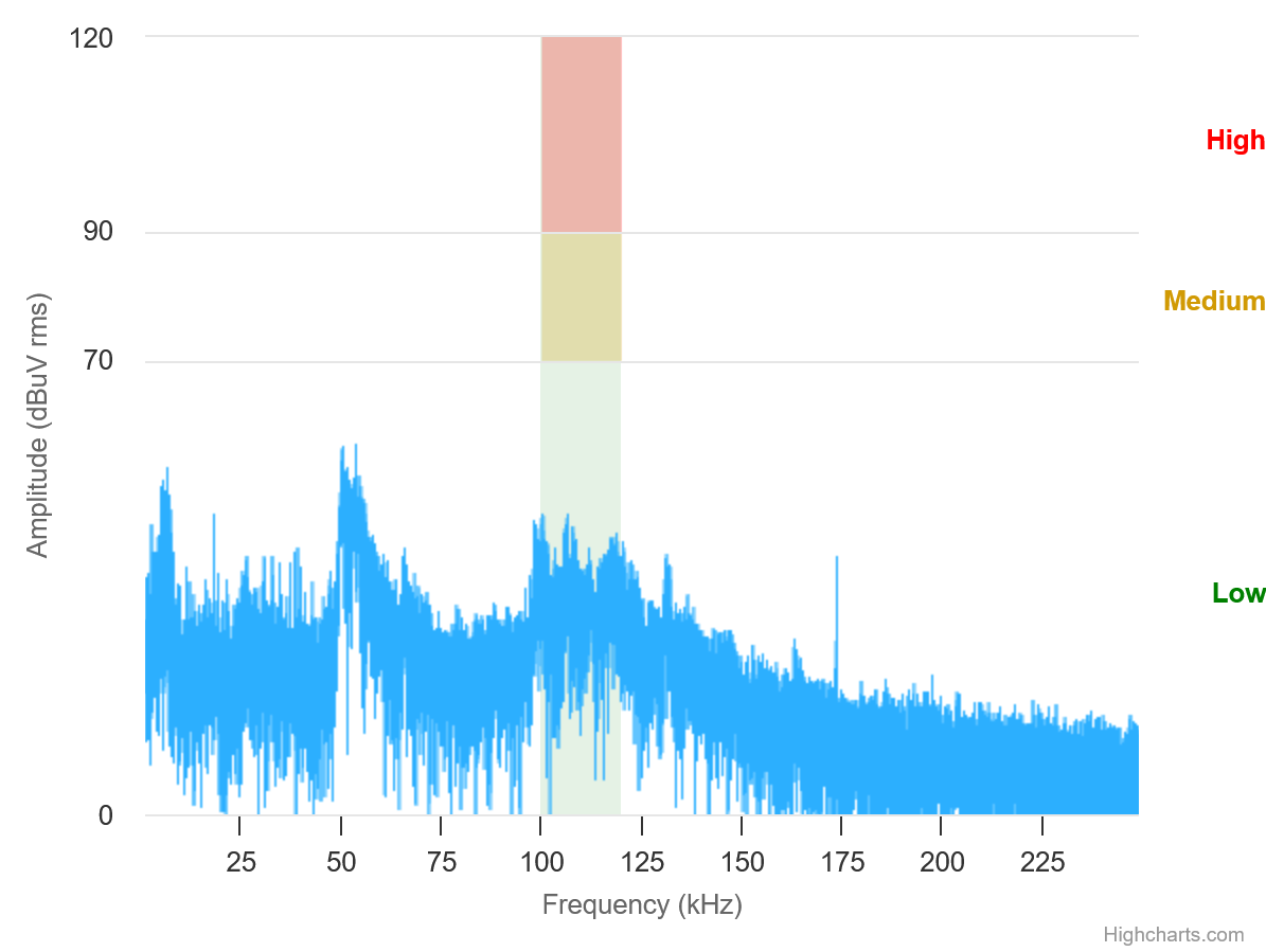
at the noisy environment, it is easy to reduce the noise signifcantly,
But, it is really hard to reduce the noise when quiet (under 50dBuV) environment.
1. Will getting worse
2. Not related with GRID - no need to check grid or profile
3. Just power on reset - at first power on reset, it is showing 'Grid Instability Error' because no grid profile
https://support.enphase.com/s/question/0D52G00004ZVmwjSAD/anyone-else-having-issue-with-some-of-their-iq7-microinverters-randomly-dropping-out-around-the-same-time-every-day
https://support.enphase.com/s/question/0D53m00007P62ncCAB/grid-instability-issue-anyone-have-similar-issue-
I have requested a detail information abut LCF-064-1P,
Enphase - datasheet only
Manufacturer - can not provide it because customized item
No more solution with LCF, I have decided to return the filter on Enphase,
I am not sure the part is no good, or filtering is not enough.
So, I start to find the solution on my way,
I have reinstalled RP230-30-10-S and GTX-2300
BUT, it has too high line loss, so, I have disassembled & checked GTX-2300.
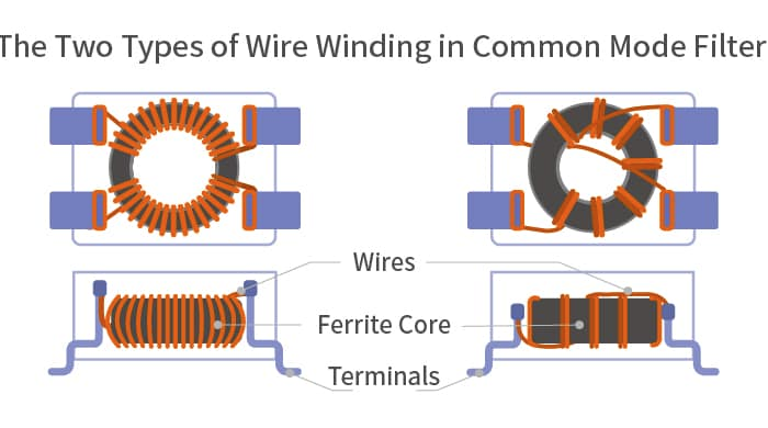
the coil configuration is the two-in-hand winding, it is good for common mode filtering, But, it has lower magnetic
leakage, so,not good for differential mode filtering. it is not much useful for me.
so, I have removed it. and, reduce 0.5mA leakage current & 10mOhm Resistance Loss
RP230-30-10-S have 60dB 50/50 insertion loss, but, can not block
the signal from next door also, I guess, my noise level at my home is too quiet and no one use PLC devices.
Yes, high SNR, so, just Envoy signal can be detected too easily.
so, I have decided to add an extra differential mode filter using ferrite
Ferrite core is B64290L0082X065
and, look the wire direction, it is the coupled differential mode, and 2 turns.
over one day, it can isolated successfuly, the expected core loss is 200-300Wh per year.
it is much less than 1~2kWh in GTX-2300-Y02.
This configuration will be saturated under 10A. so, I have tried on single turn.
at least, I need 20A because higher current will act as a noise, and will reduce the sensitivity of enovy.
and, I just need this inductor is working at the lower current (quite) zone.
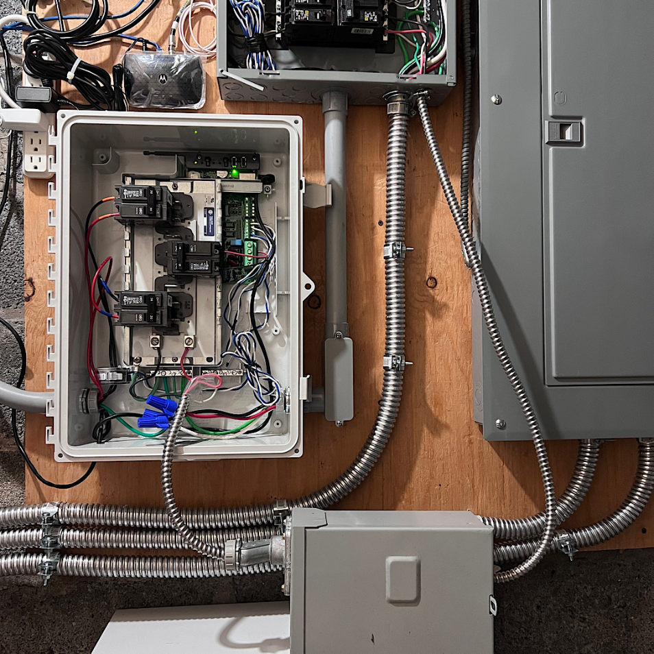
This is final configuration.
It is working well, now, my system has been isolated completely.
and, no more cross-domain-traffic issue.
The cost of Ferrite & RP230 filter is just $80, and under $100 include tax & shipping.
It will working when system current is under 24A (around 20, IQ7+),
If want to apply on the bigger system, need bigger filter
I have installed shortest wiring, and no overlap to avoid a crosstalk, and just put one Ferrite core to filter a common mode for wire organizing and 10cm overcome earth wires. It may affect on the high frequency, but, it is not our concern because LCF is for 110kHz L-to-L PLC & Noise filtering now.
Let me check what will happening,
Updated on NOV 29 2021
Long story is short, It is not working
This is an error what I do not want to get..
I have requested some advice and, Enphase said
Avoid a magnetic PLC coupling by
- Own enclouser :: it is related with a distance, but, -.-a
- 12" distance between conductor :: point to point is not important, parallel run is the key
Anyway, I have installed as
If I add an enclouser for the filter, I have to get a permit & inspection from local office. it become so complicated issue. and, I feel, so strange, the engineer do not understand what is the real problem.
anyway, I am not sure what is the cause why it can not block the signal from my next door,
i understand as it is a customized part for IQ. Maybe it is just a issue of my part.
while low current, Enovy is detecting the other enovy at outside.
IT is happening because my house has very quite in electric noise.
if not cut-out completely, the filter is not enough because still high SNR.
Very good video what is difference between Mico and String Inverters
You have to watch it before install a solar system.
Enphase MI system is much expensive than String inverter,
even more than Optimizer system.
But, String inverter system need 6+ panels in series, it means there is a minimum number of panels under similar sun-light condition. but, MI system do not have the minimum requirments, technically 1 panel.
so, if have small zone & multi zones (more than 2), MI should be better
except this condition, There is no advantage via the extra cost
https://www.youtube.com/watch?v=UQ9Szhl1ceQ
Have to watch this video ~ Really ~ Really important
Most solar users are fooled by the micro inverter company,
Their advertizing is a fake ~
Typical FAKE INFORMATION
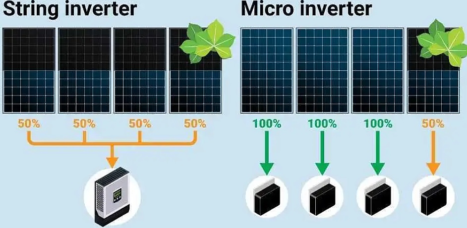
String Inverter
The pannel has connected in series. when some panel has shaded, it will affect on VOLTAGE not current. so, and, power will be by-passed on the the shade panel, total power output will be 100-100-100-50, the drawing for string inverter is 100% fake, or they just ignore the role of by-pass dioe,
Micro Inverter
when partial shading, it will reduce the voltage not current, and there are 3 or 4 sections in a panel, and each section has by-passed using a diode. if the panel has 3 sections (60-72 cell), voltage will drop to 2/3 level. Even shade a SINGLE cell. if 36~39V system voltage drop to 2/3, the votlage output with the same current will be 24~26V. UNFOTUNATELY, most micro inverter need higher than 27V, effectively 29~30V. So, Even 1 CELL has shaded, MI will just output 5-10% power which has generated by the diffusion light. so, 100-100-100-10 are the correct otuput in the drawing.
NEVER FOOLED, Practically, String inverter will ouptut more than 99% of MI system, even better long term.
If someone ask, when MI system is better ?
I want to say when have small sections. you need at least 6+ panels for start-up and 8~12 panels for the best efficiency in a section (similar light condition). and, the most string inverter has 2~4 MPPT line. if there the section size is less than 6, can not use the section in case of string inverter. and, if the section number is more than 4, need multiple inverters. example,
BUT, micro inverter system free from this requirments.
It is the real advantage of micro-inverter system,
Any other explanations are 99% BS